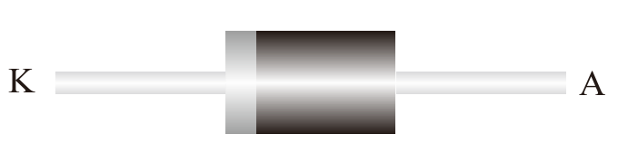
DO-27 · Datasheet illustration
Schottky rectifier diodes
SR560
60 V single Schottky rectifier in a DO-27 package. Average forward current is 5 A for the total device, under the datasheet load and thermal conditions.
Repetitive peak reverse voltage
60 V
Rating
Conditions
Maximum repetitive peak reverse voltage, VRRM; TA = 25 °C unless otherwise specified.
IF(AV), total device
5 A
Rating
Conditions
Single diode. TA = 25 °C unless otherwise specified. Single-phase, half-wave, 60 Hz; resistive or inductive load. Derate current by 20% for capacitive load; see datasheet derating curve.
Forward voltage per diode
0.7 V
Maximum
Conditions
IF = 5 A; TA = 25 °C; per diode. Pulse test: 300 µs, 1% duty cycle.
Product status: MP
PRODUCT OVERVIEW
A closer look at SR560.
60 V single Schottky rectifier in a DO-27 package. Average forward current is 5 A for the total device, under the datasheet load and thermal conditions.
- Planar Schottky barrier technology
- Low forward voltage drop
- Single rectifier diode
Technical specifications
- Repetitive peak reverse voltage
60 VRating
Maximum repetitive peak reverse voltage, VRRM; TA = 25 °C unless otherwise specified.
Datasheet p. 1- IF(AV), total device
5 ARating
Single diode. TA = 25 °C unless otherwise specified. Single-phase, half-wave, 60 Hz; resistive or inductive load. Derate current by 20% for capacitive load; see datasheet derating curve.
Datasheet p. 1- Forward voltage per diode
0.7 VMaximum
IF = 5 A; TA = 25 °C; per diode. Pulse test: 300 µs, 1% duty cycle.
Datasheet p. 1- Diode configuration
Single
Polarity diagram in the datasheet.
Datasheet p. 1- IF(AV), per diode
5 ARating
Per diode. TA = 25 °C unless otherwise specified. Single-phase, half-wave, 60 Hz; resistive or inductive load. Derate current by 20% for capacitive load; see datasheet derating curve.
Datasheet p. 1- Non-repetitive surge current
120 ARating
Per diode; 8.3 ms single half-sine wave superimposed on rated load; TA = 25 °C unless otherwise specified.
Datasheet p. 1- Reverse leakage current
80 µAMaximum
TA = 25 °C; VR = 60 V (VRRM).
Datasheet p. 1- Junction temperature range
-55 to 125 °CRange
Operating junction temperature.
Datasheet p. 1
Values apply under their stated conditions. The datasheet includes the complete ratings, curves and package information.
Documents & downloads
SR560 datasheet
PDF · English · A/1 · 2014-10-20
Typical applications
- Switch-mode power supplies
- Fast chargers
- LED drivers and monitor lighting
Application selection guides
Explore the circuit requirements for this component family and evaluate the device against your design conditions.