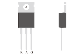
TO-220C · Datasheet illustration
Silicon controlled rectifiers
UT30-35C12
1200 V, 30 A SCR. RMS current is specified at TC ≤ 40 °C. The original datasheet includes gate drive, holding current, surge and thermal characteristics.
Repetitive peak off-state voltage, VDRM
1200 V
Maximum
Conditions
Repetitive peak off-state voltage.
RMS on-state current, IT(RMS)
30 A
Maximum
Conditions
TC ≤ 40 °C; RMS on-state current rating.
Gate trigger current, IGT
35 mA
Maximum
Conditions
VD = 12 V; RL = 140 Ω; TA = 25 °C.
Product status: MP
PRODUCT OVERVIEW
A closer look at UT30-35C12.
1200 V, 30 A SCR. RMS current is specified at TC ≤ 40 °C. The original datasheet includes gate drive, holding current, surge and thermal characteristics.
Technical specifications
- Repetitive peak off-state voltage, VDRM
1200 VMaximum
Repetitive peak off-state voltage.
Datasheet p. 1- RMS on-state current, IT(RMS)
30 AMaximum
TC ≤ 40 °C; RMS on-state current rating.
Datasheet p. 1- Gate trigger current, IGT
35 mAMaximum
VD = 12 V; RL = 140 Ω; TA = 25 °C.
Datasheet p. 2- Average on-state current, IT(AV)
20 AMaximum
TC ≤ 40 °C; average on-state current rating.
Datasheet p. 1- Holding current, IH
120 mAMaximum
IT = 500 mA; TA = 25 °C.
Datasheet p. 2- Peak on-state voltage, VTM
1.65 VMaximum
IT = 55 A; pulse width 380 µs; TJ = 25 °C.
Datasheet p. 2- Junction temperature range
-40 to 125 °CRange
Operating junction temperature range.
Datasheet p. 1
Values apply under their stated conditions. The datasheet includes the complete ratings, curves and package information.
Documents & downloads
UT30-35C12 datasheet
PDF · English · A/1 · 2014-10-20