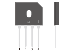
GBU · Datasheet illustration
Fast recovery bridge rectifiers
RGBU406
600 V, 4 A single-phase fast recovery bridge rectifier in a GBU package. Current and reverse recovery ratings retain their test conditions.
Repetitive peak reverse voltage
600 V
Maximum
Conditions
Maximum repetitive peak reverse voltage; TA = 25 °C unless otherwise specified.
Average rectified output current
4 A
Maximum
Conditions
With heatsink at 100 °C; TC identified in the p. 2 derating curve. Note 2: device mounted on a 250 mm × 250 mm × 2.0 mm aluminum plate heatsink. Single-phase, half-wave, 60 Hz, resistive or inductive load; derate current by 20% for a capacitive load.
Reverse recovery time (trr), max
350 ns
Maximum
Conditions
IF = 0.5 A; IR = 1.0 A; IRR = 0.25 A; TA = 25 °C.
Product status: MP
PRODUCT OVERVIEW
A closer look at RGBU406.
600 V, 4 A single-phase fast recovery bridge rectifier in a GBU package. Current and reverse recovery ratings retain their test conditions.
- Single-phase four-diode bridge
- Fast recovery rectifier technology
- Forward voltage specified per diode
Technical specifications
- Bridge configuration
Single-phase bridge
Four-diode bridge connection and two AC terminals shown in the p. 1 polarity diagram.
Datasheet p. 1- Repetitive peak reverse voltage
600 VMaximum
Maximum repetitive peak reverse voltage; TA = 25 °C unless otherwise specified.
Datasheet p. 1- Average rectified output current
4 AMaximum
With heatsink at 100 °C; TC identified in the p. 2 derating curve. Note 2: device mounted on a 250 mm × 250 mm × 2.0 mm aluminum plate heatsink. Single-phase, half-wave, 60 Hz, resistive or inductive load; derate current by 20% for a capacitive load.
Datasheet p. 1- Non-repetitive surge current
135 AMaximum
8.3 ms single half sine-wave superimposed on rated load; TA = 25 °C unless otherwise specified. See the p. 2 surge curve.
Datasheet p. 1- Reverse recovery time (trr), max
350 nsMaximum
IF = 0.5 A; IR = 1.0 A; IRR = 0.25 A; TA = 25 °C.
Datasheet p. 1- Reverse recovery time (trr), typ
220 nsTypical
IF = 0.5 A; IR = 1.0 A; IRR = 0.25 A; TA = 25 °C.
Datasheet p. 1- Forward voltage per diode
0.98 VMaximum
Per diode; IF = 4 A; TA = 25 °C. Pulse test: 300 µs pulse width, 1% duty cycle.
Datasheet p. 1- Reverse leakage current
5 µAMaximum
TA = 25 °C; VR = VRRM.
Datasheet p. 1- IF(AV), without heatsink
2 AMaximum
Without heatsink at 100 °C, as stated in the p. 1 current-rating table; see p. 2 derating. Single-phase, half-wave, 60 Hz, resistive or inductive load; derate current by 20% for a capacitive load.
Datasheet p. 1- Junction temperature range
-55 to 150 °CRange
Operating junction temperature range.
Datasheet p. 1
Values apply under their stated conditions. The datasheet includes the complete ratings, curves and package information.
Documents & downloads
RGBU406 datasheet
PDF · English · A/1 · 2014-10-20
Typical applications
- Switch-mode power supplies
- LED drivers
- Adapters and chargers